As Monkito caught fire due to internal power supply failure, I had the opportunity to redesign the PCB to have a cleaner build, to save space and to improve connections efficiency. The code has been updated as well, with some changes including EEPROM storage of brightness value, minor pinout modifications, among others.
The PCB has been sent to seeedstudio to be professionally made and the result was excellent, with clean and precise tracks and very clean solder areas. Great !
The bare PCB is available for CHF 8.00 plus shipping. If interested, please send your request to eliadarkroom at g mail, I would be glad to ship them.
The Gerber files are available by email upon request as they are not uploadable on wordpress.
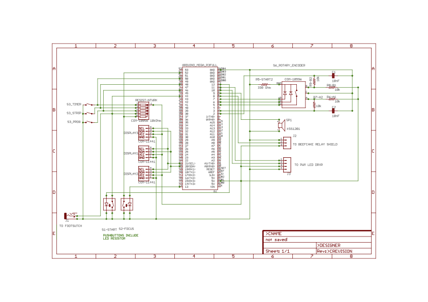
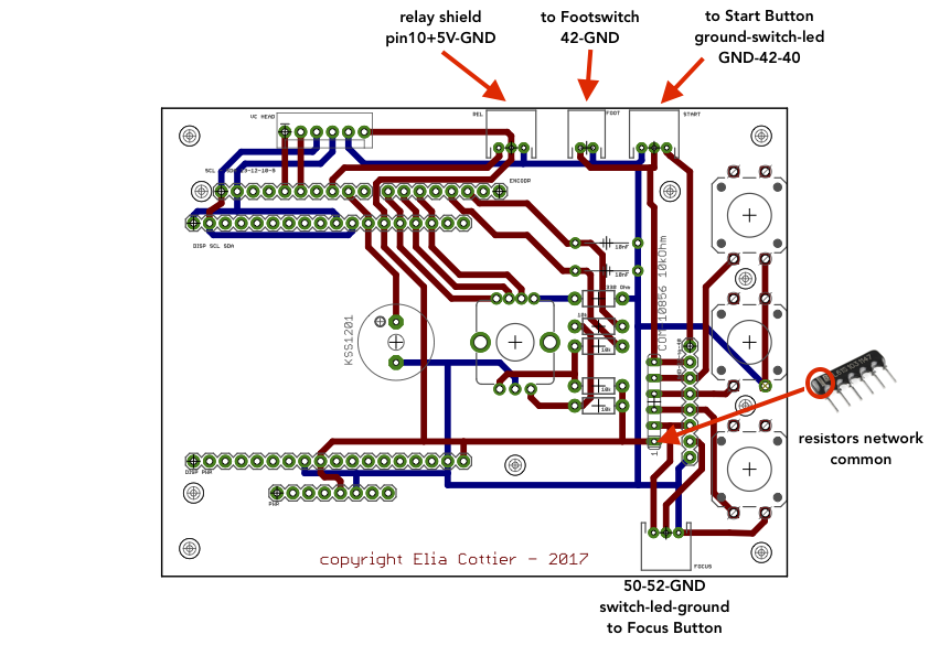
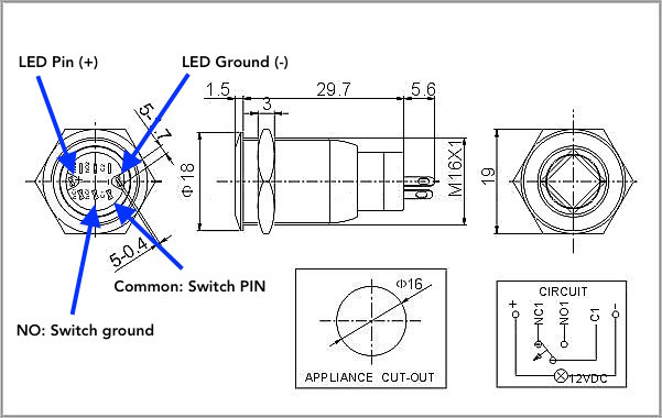
The board pinout :
please note that the pinouts for the focus and start buttons connectors are different, and the relay connector is not NOT in the same order as onto the shield (relay shield middle position: signal):
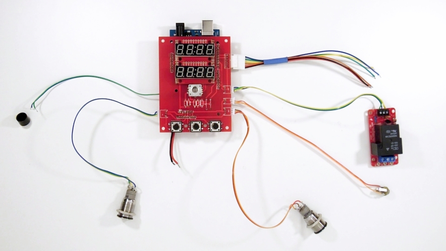
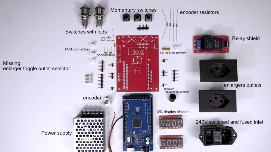
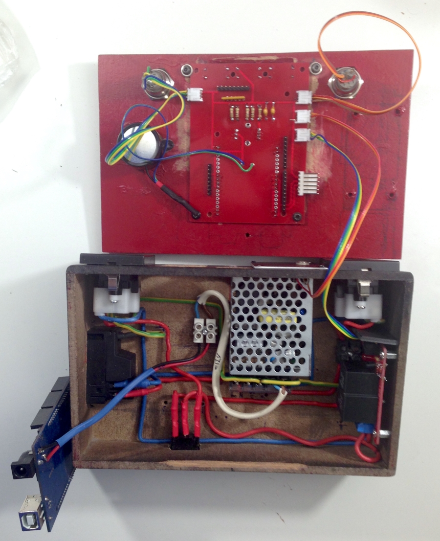
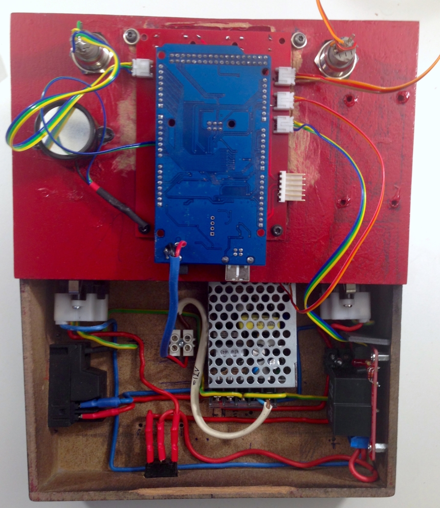
The PCB and Arduino installed / hooked up (note that the small speaker has been replaced by a louder piezo, with the advantage of allowing PWM tone modulation, not Mozart yet but still better than bzzzzzzzzzzrrrrrrrr:
A note in case of strange and odd behaviors:
In case you encounter odd display behavior, unwanted restart/reboot, apparent freeze or any erratic behavior, it is probable that your system is experiencing decoupling problems. (more about de-coupling here).
Despite I had NO problem at all during more than 9 months, yesterday I experienced what british car owners do know very well as “the Lucas syndrom”…. due probably to modifications in the building power supply where presence detection based automatic fluorescent lighting has been recently installed. Starters create all sort of nasty surges, clearly audible on my hifi system and visible on the timer (crazy displays, freeze, reboot….).
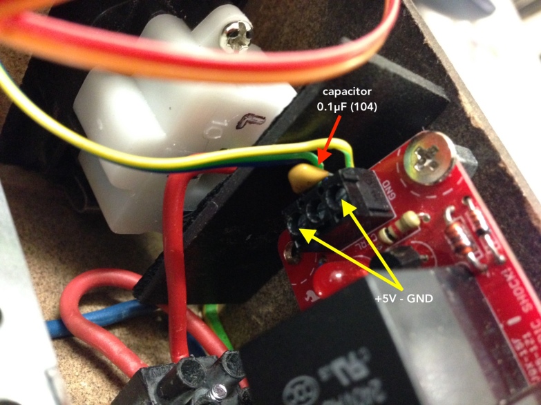
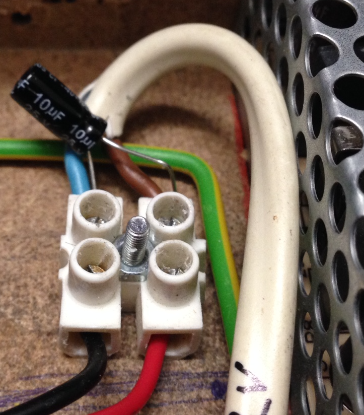
Fortunately, the solution is very simple and all you need is just two capacitors:
1 polarized 10m𝛍F to be inserted between the + and – wires of your board DC power supply (low voltage from your power supply, in my case 12V, reduced to 10.9V on the power supply itself by turning the power supply output adjuster, see the MeanWell documentation)
1 simple 0.1𝛍F (104), to be inserted between the +5V and Ground wires at the Relay Shield screw terminal (positions 1 and 3).