Arduino diy open-source darkroom f-stop timer
This article explains briefly why using f-stops as timing units, instead of seconds, does make a lot of sense in the darkroom, and why I decided to build my own timer instead of purchasing one.
The timer in action video here
Why f-stops are better than seconds, imho?
Well, f-stops are not better than seconds, any timing device and charts do the job well. F-stops are simply way more practical in the darkroom. In fact, f-stop for the darkroom is the perfect companion to the Zone System as it allows to keep using the same rationale and reference system, from shooting to printing, from the light-meter to the enlarger, or from the very first sight at the scene to the final dry print. It also greatly simplifies the darkroom maths and test prints, especially if using the split-grade method.
Much more by Gene Nocon
Said that, since my plunge into the darkroom adventure, I used a collection of dedicated darkroom timers, some basic, some excellent, some over-complicated, some not-too-bad, none of them perfect or at least adapted to split-grade.
- a loud ticking Swatch over my left dumbo-style ear. Perfect for timing, but no ear flapping allowed
- some BIG dial analog clocks and timers such as Gralabs and Haucks, very robust, yet clunky and less than precise and/or repeatable, not the best visibility in the dark, no programming feature
- electronic timers such as Kearsarge, LPL, Durst, Gossen, Wallner, very precise and excellent visibility. The LPL ET-500 and Kearsarge 301 are great tools, very robust and reliable, yet too basic. The Gossen 2000 and Wallner MC505 have awfully complicated interfaces, the excellent Durst Digitim S 1000 being the best compromise, but misses real sequence programming features and uses +/- buttons for setting times which I believe to be simply a great ergonomic swindle.

Considering the RH Designs StopClock the closest to my new darkroom whim, and having some (long) spare time to recover from traffic accident injuries, I decided to build my own, starting with a pair of to-do lists, inspired by Gene Nocon, William Brodie Tyrell, Henke Petersson, the Timerino guys in Italy and the great Arduino community.
for the timer:
- dual bright display: f-stop + seconds
- automate the test-strip process
- simplest interface/commands, without +/- buttons
- sequence exposure program
- cover, uncover, single exposure modes
- calculate print enlargement correction factors
- simplest time input method possible
- two selectable enlarger outputs ( I use two enlargers )
- safe (not keen to try 240V Electroconvulsive Therapy)
for myself:
- learn about Arduino hardware
- learn the Arduino programming language
- learn safety best practices for main power supply
- keep hardware costs as low as possible, possibly under 100 CHF/USD/EUR
Here is the result:
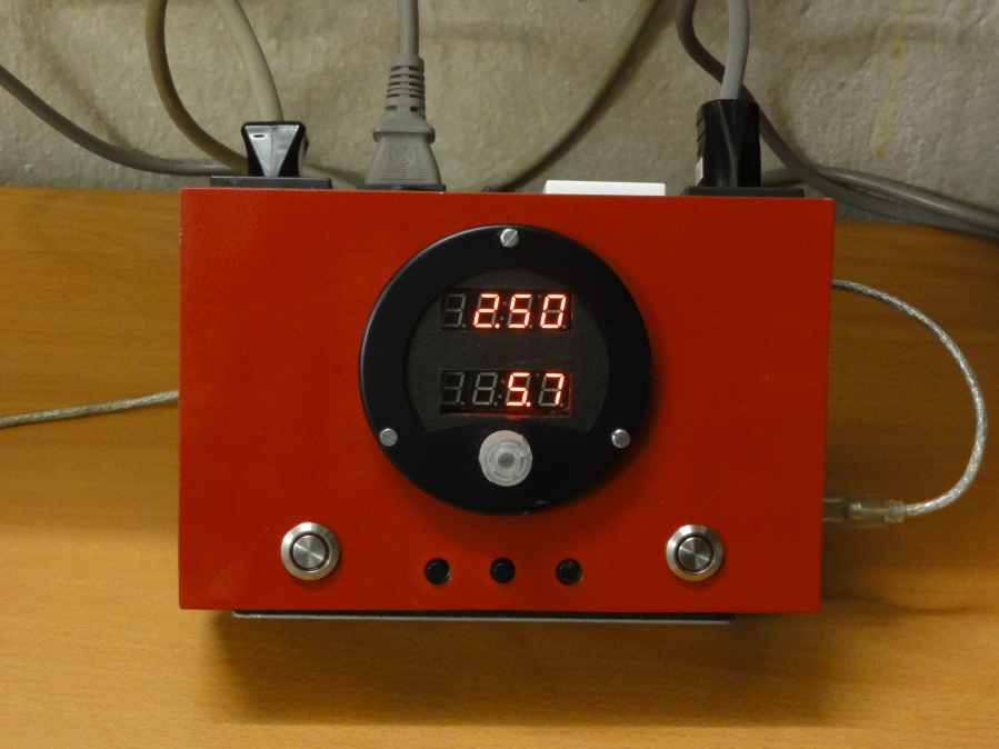
What it does as a timer:
- Simple ticking countdown timer, start/stop & resume
- Precision < 1% (measured on output relay)
- 5 channels automated test strips, 11 zones each (remember the Zone System ?)
- Specific test strip zone recall for countdown
- 5 channels for exposure programs, max of 11 steps each
- Automated print scaling time correction
- Cover, uncover, single mode exposure for both test strips and programs
Some hardware features:
- Red panel for better visibility under safelight
- Rotary selector (no +/- buttons)
- Switched and fused 240V main input
- Two selectable enlarger outputs (500W)
- One switched safelight output
- USB plug for future firmware updates
- Focus and Start/Stop led switches
- One jack plug with two serial footswitches for remote start/stop (one per enlarger)

text and images © Elia Cottier 2017 – 2019

This looks great.
Can you indicate which enlarger light source this is set up for/compatible with?
LikeLike
Thanks,
I am still in the head building process. The LED module should take the bulb place without having to modify the original head, except maybe for a hole to run a cable.
When finished I wil post a vid and schematics.
Cheers
LikeLike
Greetings from Graz!
Awesome timer design. I like the foot switch too!
I’m building my own for fun out of old bits I have lying around for my old Durst 606. (https://i386.com/darkroom-timer-wemos-esp8266/).
Gavin
LikeLike
Thanks Gavin and congrats for your projects ! https://i386.com
LikeLike
Great job
where can i find the email adress to get the gerber file please
i ‘m back in darkroom after a long pause
thank you
Thierry
LikeLike
Hi Elia!
I really love you project. Can I ask you what kind of encoder did you use? Because all encoders I find online are with 5 pins while your is with 7 pins (4+3)…
Thank you ^_^
LikeLike
Hi Elia! I really love your work! This timer is literally amazing!
Can I ask you what rotary encoder did you use? Because your has 7 pins (4+3) but I can’t find it online, I find only 5 pins encoders… 😦
LikeLike
Hi Ale, the complete BOM with suppliers references is available here: eliadarkroom.wordpress.com/monkito-pcb/monkito-bom/
Grazie per il complimento, auguri !
LikeLike